18 TCP Calibration
18.1 Overview
The TCP (Tool Center Point) calibration tool allows you to calculate the exact position and orientation of your tool tip relative to the robot flange. An accurate TCP is critical for precise cutting — especially with large sawblades where even a fraction of a degree of tilt causes grinding instead of cutting.
The calibration is based on the 4-point method: the operator jogs the robot so the tool tip touches a fixed reference point from at least 4 different orientations. AbbyCam collects the flange poses and solves the TCP offset mathematically.
The result is a complete RAPID tooldata declaration ready to paste into RobotStudio.
18.2 Requirements
- ABB IRC5 controller with 616-1 PC Interface option installed
- RAPID socket server (
T_COMtask) running on the robot - AbbyCam connected to the robot (green status indicator)
- A sharp calibration pin mounted on the robot flange
- A fixed reference point in the cell (sharp pin, machined cone, etc.)
18.3 Robot Connection
The status indicator in the dock title bar shows the current connection state:
- 🟢 Connected — AbbyCam is communicating with the robot
- 🔴 Disconnected — No connection. AbbyCam will retry automatically every few seconds.
If the indicator stays red, check:
- Robot controller is powered on and running
T_COMtask is running (check FlexPendant or RobotStudio Operator Window forCom: Server listening on port 5000)- IP address and port are correct in Settings → Rapid
18.4 Settings
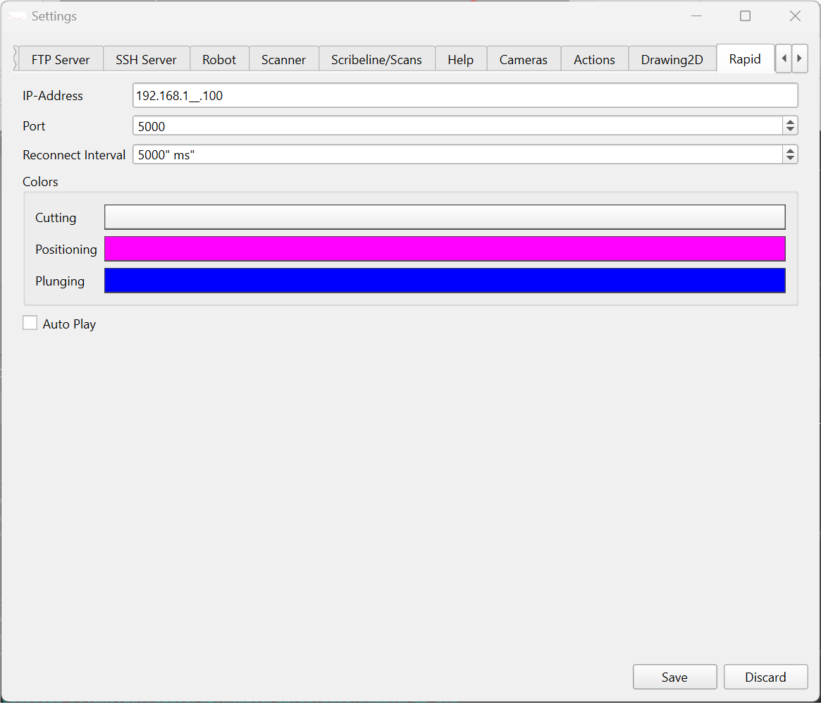
The following settings are available under Settings → Rapid:
| Setting | Description | Default |
|---|---|---|
| Robot IP | IP address of the IRC5 controller | 192.168.1.100 |
| Port | Socket server port | 5000 |
| Reconnect Interval | How often AbbyCam retries connection | 5000 ms |
18.5 Calibration Workflow
18.5.1 Step 1 — Prepare the Cell
- Mount a sharp calibration pin on the robot flange
- Fix a reference point rigidly in the cell — it must not move during calibration
- The reference point must be reachable from at least 4 very different robot orientations
18.5.2 Step 2 — Capture Points
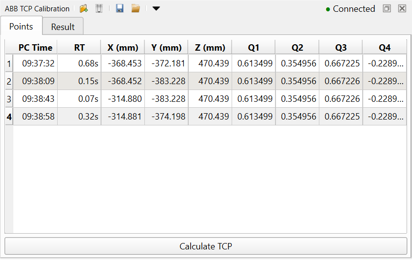
Open the ABB TCP Calibration dock and go to the Points tab.
For each touch point:
- Jog the robot carefully until the pin tip touches the reference point exactly
- Click Capture from Robot in the toolbar — AbbyCam reads the current flange pose directly from the robot
- Verify the row appears in the table with a green or yellow response time indicator
- Back off and jog to a completely different orientation
- Repeat at least 4 times — more points give better accuracy
Each pose must have a significantly different robot orientation. Simply moving the flange to a different position without rotating is not sufficient — the quaternion values must differ between rows.
Rows highlighted in yellow have a high response time (RT). This means there was a significant delay between when the robot recorded the position and when AbbyCam received it. The data may be stale — consider recapturing that point.
18.5.2.1 Point Table Columns
| Column | Description |
|---|---|
| PC Time | Time on the AbbyCam PC when the point was received |
| RT | Response time in seconds between robot and PC. -- means manually entered |
| X, Y, Z | Flange position in world coordinates (mm) |
| Q1–Q4 | Flange orientation as quaternion (ABB convention: Q1=W) |
18.5.2.2 Manual Entry
Points can also be entered manually by clicking Add Row in the toolbar. A dialog opens where you can type the values directly. Manually entered rows show -- in the PC Time and RT columns.

18.5.2.3 Saving and Loading Points
Use the Save and Load toolbar buttons to save and load point sets as JSON or CSV files. This allows you to re-run the calibration calculation without recapturing points.
18.5.3 Step 3 — Calculate
Once you have at least 4 points click Calculate TCP at the bottom of the Points tab.
AbbyCam solves the TCP offset using a least-squares algorithm and automatically switches to the Result tab.
18.5.4 Step 4 — Result
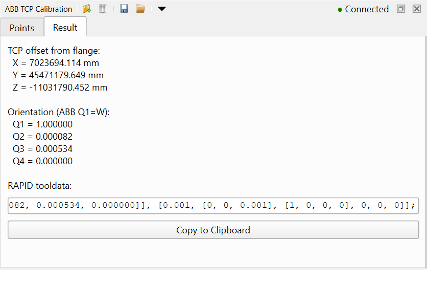
The Result tab shows:
- TCP offset from flange — X, Y, Z in mm
- Orientation — Q1–Q4 quaternion representing the tool tilt relative to the flange
- RAPID tooldata — complete declaration ready to copy into RobotStudio
The orientation quaternion captures X and Y tilt of the spindle. Rotation around the tool Z-axis (spinning around its own centerline) cannot be determined mathematically — this is expected and does not affect cutting accuracy for symmetric tools.
Click Copy to Clipboard and paste the result directly into your RAPID program in RobotStudio.
18.5.4.1 Example Result
PERS tooldata tTool := [TRUE, [[60.008, -103.598, 4.309], [0.997576, -0.047835, -0.050545, 0.000000]], [0.001, [0, 0, 0.001], [1, 0, 0, 0], 0, 0, 0]];18.6 Calibration Pin Best Practices
18.6.1 Why Tool Length Matters
Calibrating with a short pin and then using a long tool introduces errors. Any angular misalignment of the spindle mount (tilt in X or Y) is amplified proportionally to the tool length. For example, a 0.1° tilt error causes:
- 0.17mm error at 100mm tool length — acceptable for most routing
- 0.44mm error at 250mm (sawblade radius) — blade grinding instead of cutting
18.6.2 Use Matched Calibration Pins
The recommended approach is to use a set of precision calibration pins — one per tool — where each pin matches the TCP distance of the corresponding tool:
| Tool | TCP Distance | Calibration Pin |
|---|---|---|
| Router bit | 100mm | Pin A — 100mm |
| Sawblade | 250mm | Pin B — 250mm |
| Other tools | measure | corresponding pin |
Each calibration pin should be:
- Precision machined to the exact TCP length of the corresponding tool
- Perfectly concentric with the spindle mount
- Sharp tipped for accurate touch point reference
Never calibrate with the actual sawblade. Careful jogging near a reference point and rotating blades are a dangerous combination. Always use a dedicated calibration pin of matching length.
18.6.3 Workflow Per Tool
- Mount the matching calibration pin on the flange
- Run the full 4-point calibration
- Copy the result into the corresponding tool definition in AbbyCam (e.g.
tSaw,tRouter) - Repeat for each tool
This ensures that angular mounting errors are captured at exactly the right leverage arm — giving you the most accurate TCP for each tool without ever touching the real cutting tool during calibration.
The robot communication requires a background RAPID task T_COM running Com_StartServer. This task must be set up once per controller.
See T_COM Setup for step-by-step instructions.
18.7 Troubleshooting
| Problem | Check |
|---|---|
| Status always red | Is T_COM running? Is the IP correct in Settings → Rapid? |
| Capture button disabled | Status must be green before capturing |
| Result is 0, 0, 0 | All quaternions are identical — robot orientations must differ between points |
| Yellow RT warning | Large delay between robot and PC — recapture the point |
| Result seems wrong | Check that the reference point did not move during calibration |
| Can’t connect after restart | T_COM task may not have loaded — check RobotStudio Operator Window |