8 Pep (Piece en piece)
The Pep-System is a combination of Software and Hardware that produces standard parts that automatically fit together.
8.1 Pep Properties
The parameters of the single cuts are defined in a database and can be adjusted as necessary in the Pep Properties.
Those values are default values when a Pep-Part is created and can still be overwritten by changing the properties on the part.
Info! When the values are changed in the database existing panels won’t take over the new values. You need to delete a panel and create a new one.
You also can overwrite the setting in the panel parameter.
Warning! When parameters are changed in single parts they may not fit together anymore.
8.1.1 General
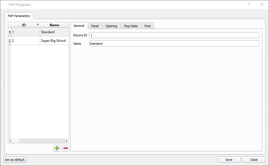
| Property | Description |
|---|---|
| RecordID | Database identifier for internal use. Will be filled automatically and cannot be changed |
| Name | Name of the properties |
8.1.2 Panel
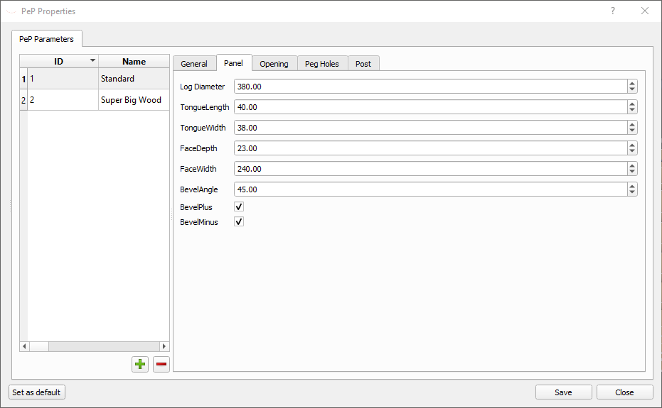
| Property | Description |
|---|---|
| Log Diameter | Average diameter of the logs in a panel |
| Tongue Length | Length of the tongue |
| Tongue Width | Width of the tongue |
| Face Depth | Distance from the post center to the face of the panel-log |
| Face Width | The width of the face |
| Bevel Angle | Angle of the Bevels |
| Bevel Plus | Cuts a Bevel on the y-plus side of the panel |
| Bevel Minus | Cuts a Bevel on the y-minus side of the panel |
8.1.3 Opening
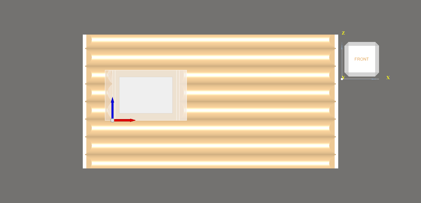
An Opening can be a window or a door.
There are multiple openings possible in a panel (vertical and/or horizontal).
Make sure the single logs are not too short after you placed the openings. A panel log needs a minimum length to work. It also depends on the part holder whether the part can be cut.
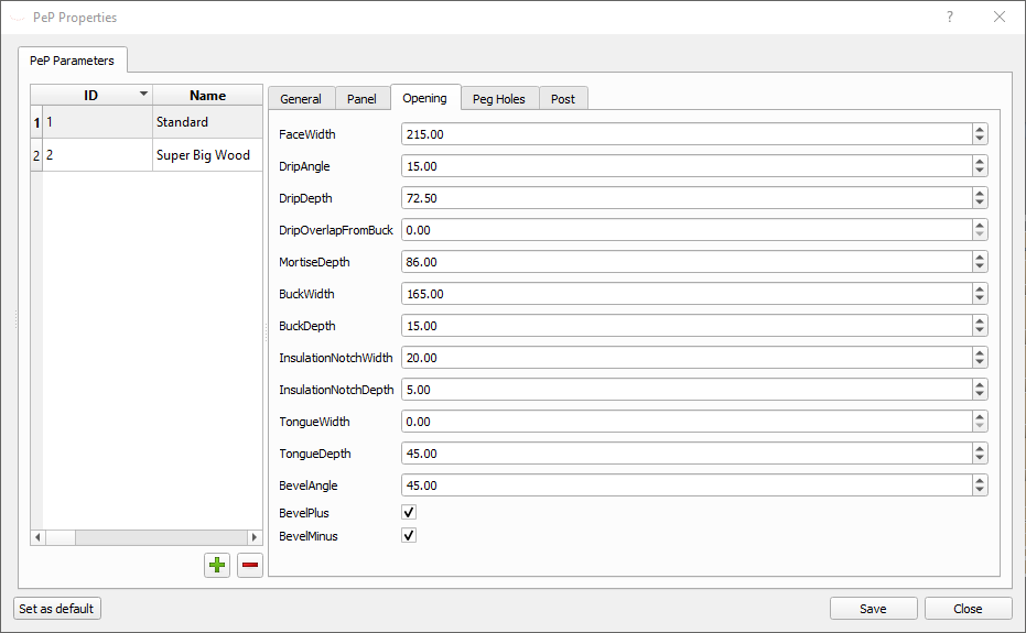
| Property | Description |
|---|---|
| Face Width | Average diameter of the logs in a panel |
| Drip Angle | Angle of the drip window sill |
| Drip Depth | Depth of the drip |
| Drip Overlap from Buck | Sets how much the drip should be ofset from the buck. Usually this is 0 |
| Mortise Depth | Depth of the mortise. |
| Buck Width | Width of the bucket |
| Buck Depth | Depth of the buck |
| Insulation Notch Width | Width of the groove for the insulation |
| Insulation Notch Depth | Depth of the groove for the insulation |
| Tongue Width | … |
| Tongue Depth | … |
| Bevel Angle | Angle of the Bevels |
| Bevel Plus | Cuts a Bevel on the y-plus side of the Opening |
| Bevel Minus | Cuts a Bevel on the y-minus side of the Opening |
See Drawing
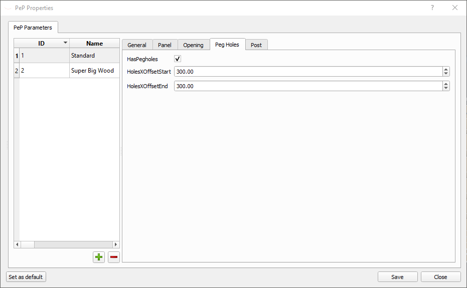
8.1.4 Peg Holes
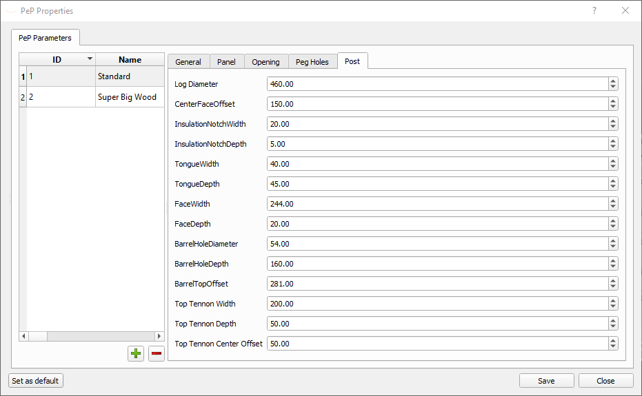
8.1.5 Post
8.2 Panels
8.2.1 Create a Pep-Panel
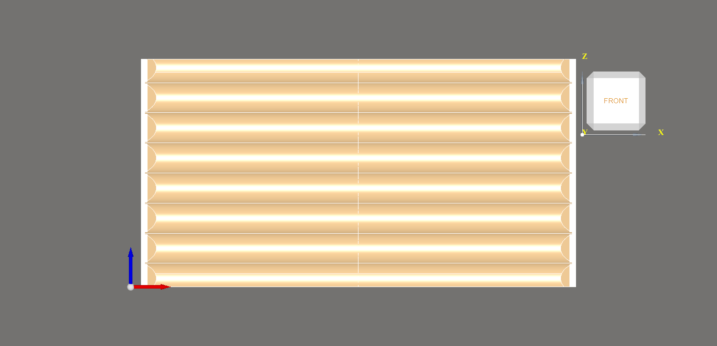
Click on the Panel symbol and a panel with default values will be created. This is model without any cuts, scribelines, scan-data etc. and the purpose is to build the model for the house. All those information will be added when the model is fix and decribed below.
8.2.2 Properties
| Property | Description |
|---|---|
| Height | The height of the panel |
| Length | The Length from Post to Post of the Panel |
| Log Diameter | Amount of logs in the Panel |
| Chinked | Panel is chinked |
| Chink Color | The color of the chinking |
| Chink Width | The width of the chinking |
| Amount Logs | The amount of logs in the Panel |
| Flat Minus | The logs are flat on the y-minus side |
| Flat Minus Offset | The offset of the flat from the center of the log |
| Flat Plus | The logs are flat on the y-plus side |
| Flat Plus Offset | The offset of the flat from the center of the log |
| Cut off top | |
| Cut off bottom | |
| Tongue Length | Length of the tongue |
| Tongue Width | Width of the tongue |
| Face Depth | Distance from the center of the post to the face |
| Face Width | Width of the face |
| Bevel Angle | Angle of the bevels if they have any |
| Bevel Minus | Enables bevel cut on the y-minus side |
| Bevel Plus | Enables bevel cut on the y-plus side |
| Peg Holes | Enables peg holes |
| Pegholes X Offset Start | Offset from the start of the log |
| Pegholes X Offset End | Offset from the end of the log |
8.2.3 Functions
8.2.3.1 Add Posts
Posts can be added on a selected end or both sides. Because Posts also can add a panel the combination of those functions makes it really easy and fast to build a model.
Add post both
Adds two posts to the panel. One at start and the other on the end.
Add post start
Adds a post to the start of the panel.
Add post end
Adds a post to the end of a panel.
8.2.3.2 Rebuild
This will create the logs in the panel.
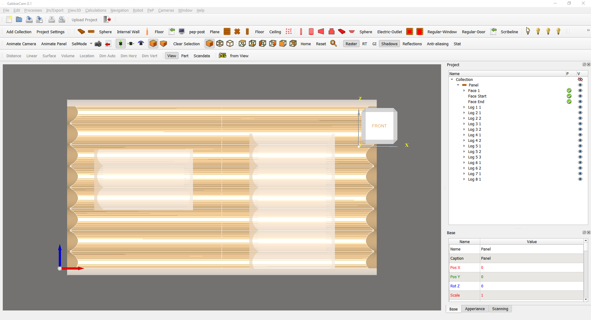
Logs are automatically be numbered by the row and amount of logs in a row. For example: If the panel has no opening at all, the Logs will be numbered
- Log 1 1
- Log 2 1
- Log 3 1
- etc
if the panel has a window then the numbering would be as follow:
- Log 1 1
- Log 2 1
- Log 3 1
- Log 4 1
- Now the window starts
- Log 5 1
- Log 5 2
- Now the window ends
- Log 6 1
- Log 7 1
- Log 8 1
Now you can add other cuts to the logs like an Outlet etc.
8.3 Panels (Scribed)
Panels can be also scribed. This means the logs in the panel are connected via a scribeline. For this all the logs in the panel need to be scanned first.
Then the scans need to be aligned for a good fit so the scribeline can be cut.
8.3.1 Load All Scans
This will load all the available scans of the panel in full resolution.
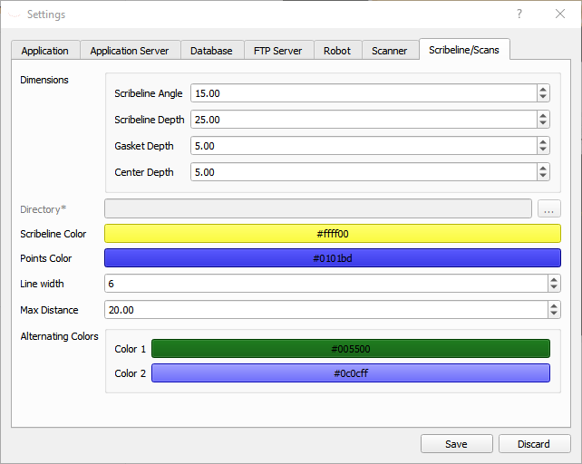
8.3.2 Alternate scan colors
This will change the colors of the scans in the panel. The colors can be set in the Settings Dialog tab Scribeline/Scans under Alternating Colors
8.3.3 Align the scans
Info! Before you begin make sure the logs are scanned properly as described here or you will have trouble to get a fast result.
The scans must be aligned in the panel the way it will be cut. Try to get the scans as close to the panel logs as possible. Since the panel is the ‘perfect’ panel, it will act like a template.
Here the optimized way to do so:
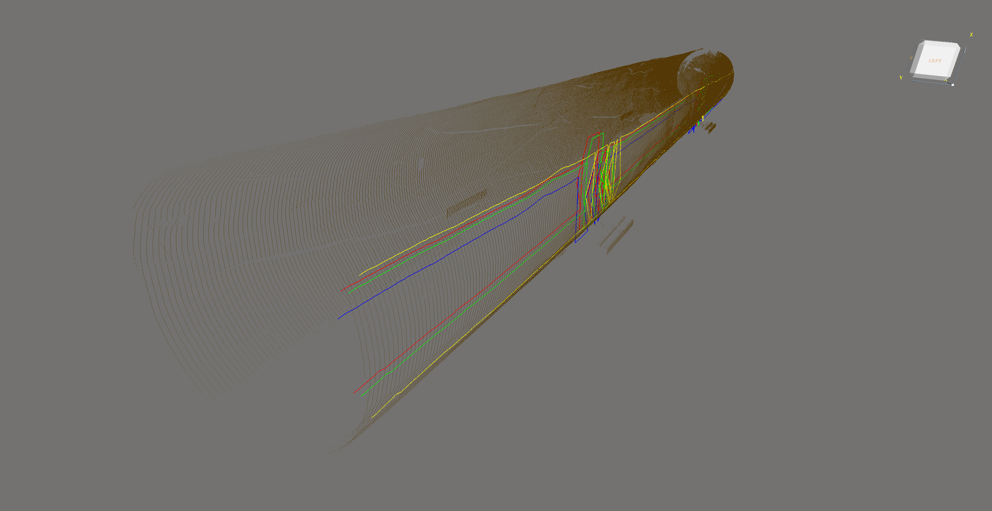
- Look from left into the plusX side. We wanna align the X-0 first
- Move the scan in the x-axis (posX) so that both ends of the scan overlappig the panel
- Bring the scans into the y-center of the panel by changing the posY value
- Move the scan up and down (posZ) untile the width of the scribline fits your needs
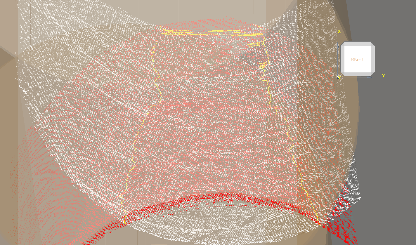
- look from right (into minusX) and get the scan centered by changing the rotations. Do not change any positions anymore (except Z to change the width of the scribline), otherwise you move the other side (left view)
- Straight out the scans that they are parallel to the panels by changing the rotZ value
- Change the rotY value on the scan to align the scan over the panels z-axis
- If necessary rotate the log over the x-axis (rotX) if there is a crack or a better fit
- Place an internal wall with the desired scribeline width.
- Look from left and move up/down the scan (posZ) until the scribeline has the same width as the internal wall.
- Look from righ and if the scribeline is wider on one side then the horizontal alignment of the scan is not perfect.
- Toggle visibility of the panel and you will see only the scans. Do final adjustments on the scans.
8.3.4 Scribeline
The scribeline is the connection between two logs and is for every log different.
To be able to calculate a scribline the ICP-Host needs to be started before GabbieCam. Find more information about the IPC-Host here
8.3.4.1 Calculation of a Scribeline (Test phase)
- create panel
- right click on the panel and choose
Rebuild and load all Scans - add Scribelibe to face Center Line on the log you wanna cut the Scribeline
- position the Scan - do not move the Log
- calculate manual via
Calculate Scribelineor set the propertyLive Updateto TRUE for automatic updates - *When finish positioning the Scan, set the transformation of the Scribeline to zero (posX=0,…, rotX=0,…).
- *In a single scan, the transformation of the Log needs to be zero (posX=0,…, rotX=0,…).
- select Create Robotcode in the popupmenu of the Log
*maybe 7 and 8 are not necessary.
If the scan is not rotated back it may look strange but the Scribeline will be in the correct position for cutting. To bring the Scribeline in the correct position for 3D-view, the scribeline needs the same transformation as the scan.
In a multiple scan, the transformation of the Log needs to be zero as well, except posX - this has to be the original position. Or so…
Warning - there is an error. The scribeline is ‘delayed’. This means the Scribeline is calculated by the last position of the scan. Easy fix: move the scan again by a small change in one of the transporming properties. Best is posX + 0.1
8.3.4.2 Calculate Scribeline
Move the scan off the log in the right position. Then select Calculate Scribeline. The scribeline will be calculated and shown in the Panel.
8.3.4.3 Modify a Scribeline
Sometimes the Scribeline jumps unexpected. This mainly happes when there is a crack and the algorythm detects a better fit in the crack. If that is not corrected then the cutter will go to the point in the crack and basically destroys the log.
r if (knitr::is_html_output()) { paste("{.class width='320px'}") }
To move a point to the correct position simply zoom in, select the point and move it to the right position wit the Manipulator
8.4 Posts
Create Posts
8.4.1 Rebuild
Warning! When rebuild, all processes will be removed. Also your custom cuts.