10 Production
10.1 Placing
Before placing the part in front of the robot make sure that the orientation (butt/tip) is correct and aligns to the part in GabbieCam.
10.2 Calibrate a part
The robot needs to know where the part is before you can start cutting. Since we don’t have a fixed coordinate system, like a CNC table, we need to define where the X/Y/Z coordinate system is and at what angle.
There are two ways to do that:
- 2/3 point measurement
- Scanner
10.2.1 2/3 point measurement
10.2.1.1 Difference between 2 and 3 point measurement
With this method we are using the robot with the tool Pin to measure the position of the part. The difference between a 2 or 3 point measurement is that the 2 point assumes that the rotation over X is 0 degrees, on a 3 point we also rotate over X.
10.2.1.2 2 Point measurement
Let’s say you want to measure a log — you have a center line through the log. You will mark the butt and tip with a marker and so define the line.
So now we have 2 points for the start and end of that center line. Go with the tool to the first point (P1) and record the coordinates (X/Y/Z values). Do the same on the other side with P2.
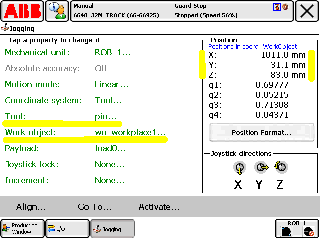
Make sure the tool Pin is selected plus the workobject you are going to cut with.
10.2.1.3 Insert the points
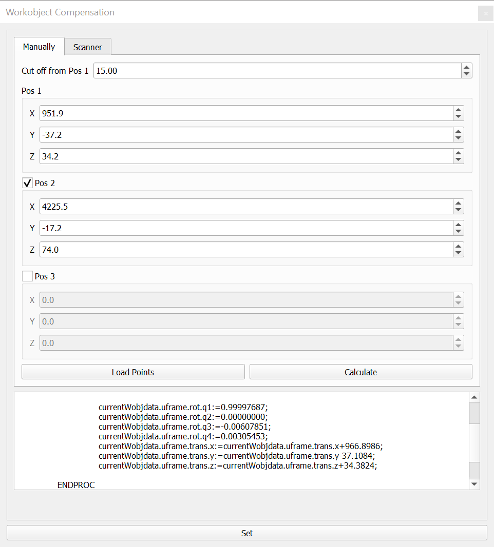
Insert the points into the dialog “Workobject Compensation”.
| Name | Description | Datatype |
|---|---|---|
| Cut off from Pos1 | Distance the zero point will be moved into the part | Double |
| Pos 1 X | X value of pos 1 | Double |
| Pos 1 Y | Y value of pos 1 | Double |
| Pos 1 Z | Z value of pos 1 | Double |
| Pos 2 X | X value of pos 2 | Double |
| Pos 2 Y | Y value of pos 2 | Double |
| Pos 2 Z | Z value of pos 2 | Double |
| Pos 3 X | X value of pos 3 | Double |
| Pos 3 Y | Y value of pos 3 | Double |
| Pos 3 Z | Z value of pos 3 | Double |
INFO: Set property scan at the log to false (means you are using 2/3 point measurement and not the scanner) and choose the same workobject you were measuring the points with.
After inserting the values press “Calculate” to calculate the values for the robot. You can see the result in the text field below. To confirm click on the button “Set” at the very bottom. Confirm to write the values to the server so the robot can read them.
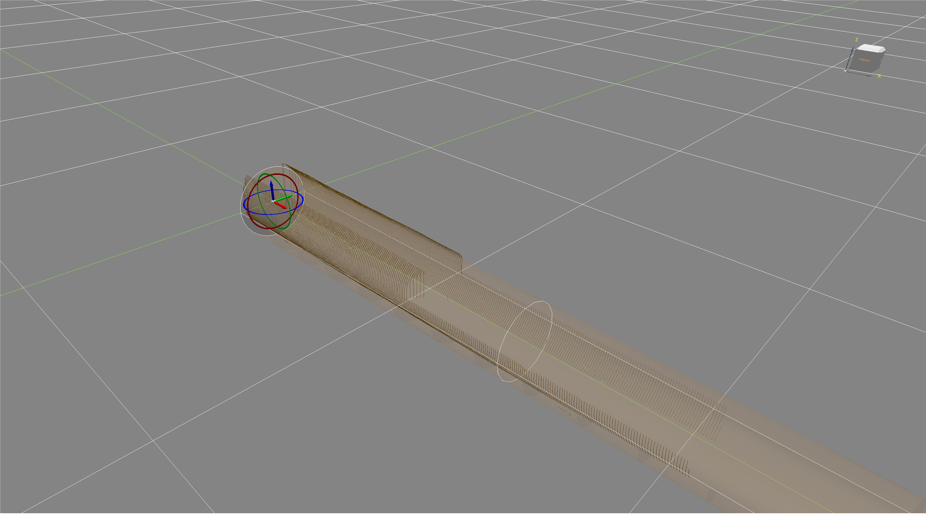
The coordinate system is now aligned as shown in the picture below and you can now start cutting.

10.2.2 Scan Orientation
If you choose Scan Orientation then you have to scan the part first and load it into the scan. Move the scan points so that the part fits nicely into it.
Set Scan Orientation in the properties to TRUE.
10.3 Post
10.3.1 Loading
- Choose fitting log by measuring tip, butt and length against the drawing
- Load the log with butt towards X0 — tip towards X+ on the wagon. Keep a longer distance at the tip side for the cut off (in case the log is too long)
- Screw the log to the wagons
- Move the log to cutting position
10.3.2 Placing
If the post is a 90 degree post then find the 2 sides that are the most straight. This has 2 advantages:
- Less wood removal
- The flair in the butt looks good from the outside of the building
10.3.3 Cutting
- Find the center with the template
- 2-point measurement with pin
- Start cutting with chainsaw for the ends
Info: There are currently some restrictions:
- Orientation of tool at top cuts with chainsaw has to be [90,0,90]
- Orientation of tool at side cuts with chainsaw has to be [-90,0,-90]
- If cutting roof angle from minus side set trackoffset 2300
- Use only 180 (top) and 270 (side) cuts. If you need 90 then inverse posY and rotY or the chainsaw runs in the wrong direction and crashes
- Top Tenon makes the spindle turn in the wrong direction and crashes the cable. So cut bottom tenon instead but check the orientation of the log first. Means butt is at the end
10.4 Panel
10.4.1 Cutting dimensions

10.4.1.1 Regular panel log
If the first scribeline is higher than the second one (happens when the bottom log starts before the log above) then the angle has to be plus -15.
Dimension is center post to center post.
Example: if center to center post is 5000mm then the cut log length is 5000 - 2x150 (face width) + 2x40 (tongue length) = 4780mm
10.4.1.2 Window end to post end
Set the length of the log from tongue to total end of the log. If you want to make a log with window to post then add the 40mm for the tongue to the opening width.
Example: if opening width is 2000mm then the log length is 2040mm.
10.4.2 Chinking
Nothing special here.
10.4.3 Scanning for scribeline
- Align the scan to the log
- Do not move the log
10.4.4 Opening
Precut with chainsaw needs to be tested.
10.5 Top Plate
Info: There are currently some restrictions:
- Orientation of tool at top cuts with chainsaw has to be [90,0,90]
- Orientation of tool at side cuts with chainsaw has to be [-90,0,-90]
- If cutting roof angle from minus side set trackoffset 2300
- Use only 180 (top) and 270 (side) cuts. If you need 90 then inverse posY and rotY or the chainsaw runs in the wrong direction and crashes