7 Scanning
- Scanning allows to place cuts without a 2 or 3 point measurement.
- The cuts are always related to the part.
- Place the scan so that the part is fully in the scan or it will cut outside of the log
7.1 Preparation
INFO: Logs need to be dry and out of the sun to be able to scan
Before you can produce a part you need to scan it.
7.1.1 Logs
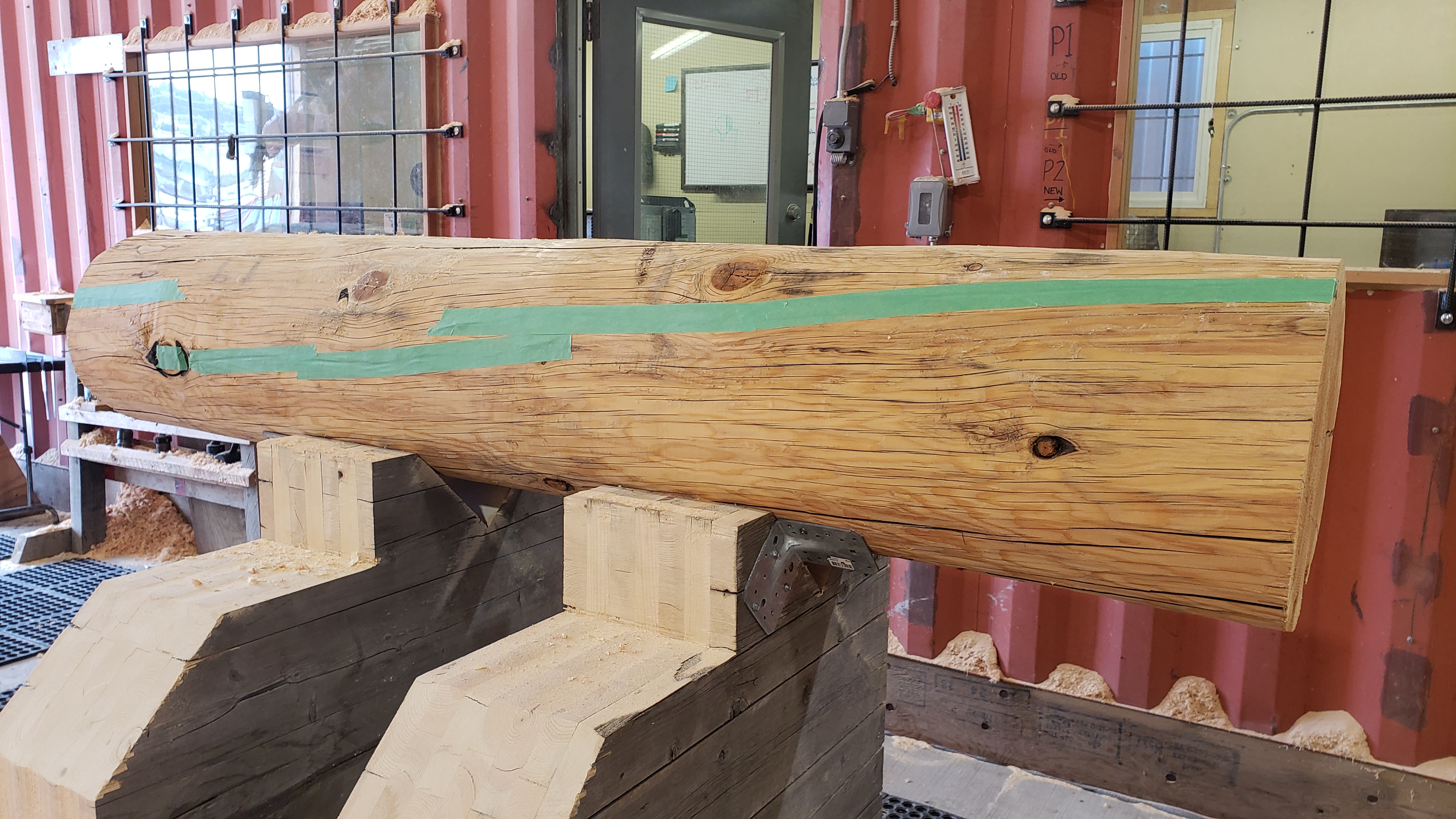
Cracks in a log can make your life really difficult when you use the scan to calculate a scribeline because the cracks will be scanned. While humans ignore the scan and still see the whole log, the scanner is seeing the cracks and will take them as what it is - a surface of the log. The resulting scribeline calculation will make it really difficult to calculate a scribeline. It can be that the calculation will find a better match in the crack than the surface. Since this is technically correct, it is not what we want.
To prevent this there is an easy solution: tape the crack with a painter’s tape. A painter tape
- is easy to attach in seconds
- is cheap and does not create much garbage
- keeps the natural shape of the log - the scan is 1:1 as there would be no crack
- easy to remove
- doesn’t leave any marks when you remove it
- the resulting scribeline calculation will be perfect

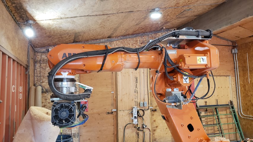
7.1.2 Hardware
Make sure the cable is in a position that it won’t be pulled or is in the way of the scanner.
7.1.3 Software
7.1.3.1 Adjust Settings
- Check settings and adjust OffsetZ and CenterOffset
- Mark X = Panel(Log) Length
- End X = Panel(Log) length + 300
7.1.3.2 Turn scanner on
- On the handheld select “Inputs and outputs”
- Select
View > Digital outputs - Mark
do_LaserPower - Set value to
1by clicking on the1on the bottom (Select0will turn off the scanner) - Wait approx 30 seconds to allow the scanner to boot up
7.1.3.3 Create the robot code
Press the button “Create Robot Code” in GabbieCam
7.2 How scanning works
A scan of a log or beam is built out of two halves. First the robot will move the scanner along the log(s) on one side and then switches to the outer side and scans in the opposite direction. This scan will be saved as tempScanData.gsc as a backup in case something goes wrong in the next steps.

Those half scans will be automatically put together so that every log has the correct half and saves the single scans to separate files.
7.3 Procedure for single-scan
Every part has a scan attached. This means every part can be scanned. This also becomes really handy for beams because they are not always 100% straight.
- Select the log in the panel that is going to be scanned
- Press Record in GabbieCam
- PP Main
- Start Robot
- The Robot will go to start position and stops when the laser is on top. Laser will be turned on for marking the log
- Move the log in so that the laser line is approx. 100mm from the log start
- Mark the log with a pencil
- Hit start again on the robot, the robot will start scanning the log on both sides
- Press Stop Recording
The log is now completely scanned and the data is saved.
7.4 Procedure to scan a Panel
A panel has multiple logs that need to be scanned. The scans will be saved under the Scandata Dir folder (settings).
There are two different ways to scan the logs for a panel:
- Single mode
- Multiple mode
7.4.1 Single mode
The single mode means you have to scan every single log alone.
The procedure is exactly the same as Procedure for single-scan, except you need to select the log in the panel you are going to scan. This will make sure that the scan is saved in the correct folder.
7.4.2 Multiple mode
In the multiple mode more than one log can be scanned. GabbieCam will scan all the logs and recognize the amount of logs. GabbieCam will choose the right data and will create single files in the background.
Make sure there is a gap between the logs of between 900mm and 1000mm to allow space to cut the ends.

Select the panel where those scans will be attached. Make sure the panel has a unique name. The scans will be saved in the Scandata-Dir folder/panel name/log_n.
Example: D:/scans/panelA1B1/log_1.gsc
Start the scan. The single scans will be created and saved in the folder. When finished, the scan will show up in the panel.
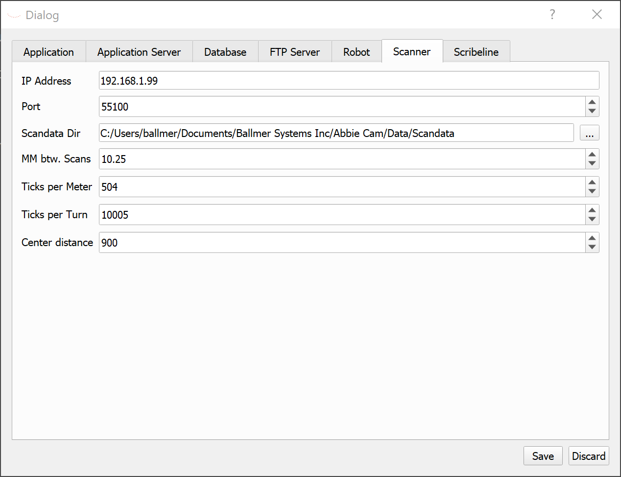
7.5 Settings
7.5.1 Scanner
For 14” log:
| Name | Description |
|---|---|
| Offset Z | 240mm |
| Center Offset | 800mm |
7.5.2 Hermary settings
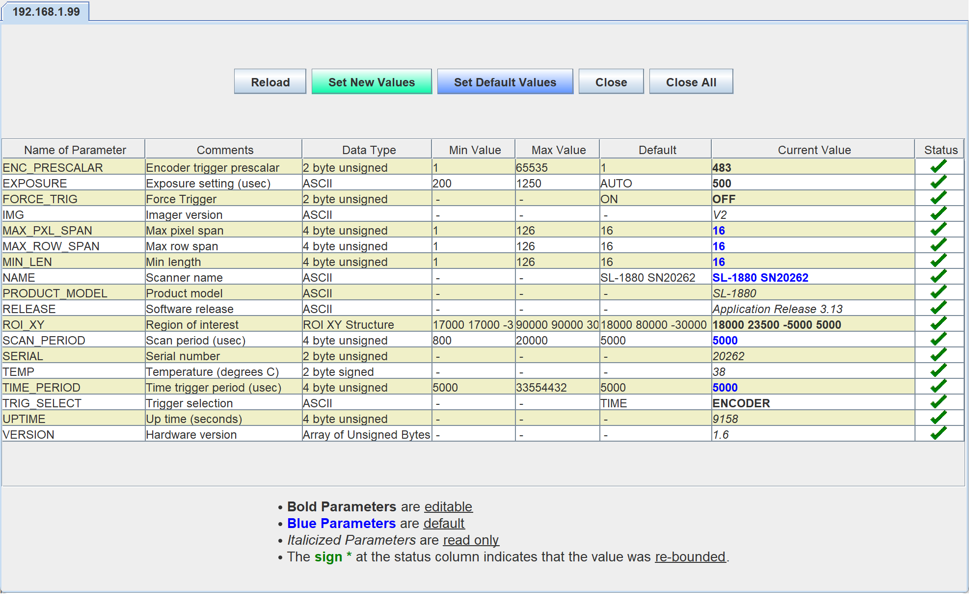
INFO: On startup the scanner Force_Trig needs to be set to ON or the scanner will not turn on.
| Name | Description |
|---|---|
| IP Address | IP Address of the Scanner |
| Port | Port where the Scan Data will be received |
| Scandata Dir | Folder where to save the data |
| MM btw. Scans | How many mm are between single scans |

7.6 Limits
Only the left and right sides of a log can be scanned at the moment.